
How to test the Midway Motherboard Edge Connector
(C) 2003-2005 Elektron Forge, All Rights Reserved
Introduction:
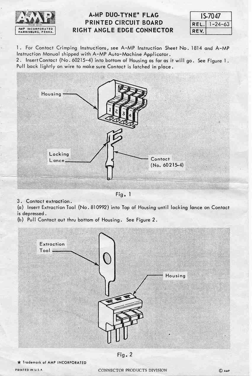
The motherboard edge connector is the source of a lot of woes. This section should help you determine if yours is in good condition or not. Here's a copy of the data sheet (vintage 1963!) that shows how individual conductors can be removed if you'd like to try to bend yours back into shape.
Hopefully you see something like this when you look in the back of your game cabinet. In the case of Midway Space Invaders and Space Invaders Deluxe, you'll see three white connectors that are used: two at the left, and one at the right. Since this is a Space Invaders Deluxe sound board that is facing us in the picture above, there is an unused third connector on the left in the middle. "Regular" Space Invaders does not have this connector.
The connector most likely to cause problems for you is the one shown on the right in the picture above. The original connector was made by AMP in the early '60s, and by 1978 improved connector designs were available. For some reason, Midway chose to use the obsolete design rather than the improved design, probably for cost purposes. At some point (probably the early 1980's) AMP discontinued the manufacture of this type of connector.
CAUTION: This test will require you to work on the game with the power on. You do so at your own risk. High voltages are not present in the areas you will be working in for this test, but lethal voltages do exist within the cabinet.
We'll start by performing the tests, and we'll deal with what to do if there are problems afterwards.
Tools Required:
For this test you will need only a voltmeter capable of measuring DC voltages from -20V to +20V or more. Almost any meter exceeds this minimum requirement, so don't worry too much about the range. You must set the meter to measure DC volts, so check the owner's manual for your meter if you aren't sure how to do that. These instructions are written for use with a digital voltmeter. An analog voltmeter cannot correctly measure negative voltages using the technique described. You'll also need a third hand. If you have good coordination, you may be able to hold both probes in one hand but be careful not to allow the probe to short against more than one trace.
Step 1: Checking the +5V Connection:
NOTE: In all of the pictures that follow, the boards are shown removed from the game for clarity only. To perform these tests for real, the boards must be installed in the game with all of the connectors in place, and the game power must be ON. The red test lead should be plugged into the + input of your meter, and the black test lead should be plugged into the - input of your meter.
With the power on and the edge connector attached, measure the +5V connection to the motherboard by placing the leads of your voltmeter on the PCB traces shown in the picture below. Most of the trace will be obscured by the edge connector housing, but there should be enough exposed to allow you to make a connection. Your meter should indicate somewhere between 4.8V and 5.2V. If necessary, adjust your power supply to make this value as close to 5.1V as possible. Refer to our "Testing the Midway Power Supply" page if you need help identifying which adjustment is for the +5V line. Using your third hand, gently wiggle the edge connector while monitoring the voltage. If the voltage fluctuates more than 0.2V, then your edge connection is bad.

Step 2: Checking the +12V Connection:
With the power on and the edge connector attached, measure the +12V connection to the motherboard by placing the leads of your voltmeter on the PCB traces shown in the picture below. Most of the trace will be obscured by the edge connector housing, but there should be enough exposed to allow you to make a connection. Your meter should indicate somewhere between 11.0V and 13.5V. If necessary, adjust your power supply to make this value as close to 12.0V as possible. It may not be possible to set the voltage at exactly 12.0V. Refer to our "Testing the Midway Power Supply" page if you need help identifying which adjustment is for the +12V line. Using your third hand, gently wiggle the edge connector while monitoring the voltage. If the voltage fluctuates more than 0.2V, then your edge connection is bad.

Step 3: Checking the -5V Connection:
With the power on and the edge connector attached, measure the -5V connection to the motherboard by placing the leads of your voltmeter on the PCB traces shown in the picture below. Most of the trace will be obscured by the edge connector housing, but there should be enough exposed to allow you to make a connection. Your meter should indicate somewhere between -4.8V and -5.2V. If necessary, adjust your power supply to make this value as close to -5.0V as possible. Refer to our "Testing the Midway Power Supply" page if you need help identifying which adjustment is for the -5V line. Using your third hand, gently wiggle the edge connector while monitoring the voltage. If the voltage fluctuates more than 0.2V, then your edge connection is bad.

Step 4: Testing the Audio Power Connection:
Assuming everything else checked out OK, we might as well make sure that the audio power connection is also OK. The voltage indicated using the test points shown below should be somewhere between 18VDC and 22VDC (the connector is removed for clarity - make sure it's connected when performing this test). The only thing this voltage gets used for is the final amplification of the sounds. If there's a problem, the game will still work OK but all the sounds will be affected.

Step 5: OK, I've done all of that, now what?
If any of the voltages were way off and your power regulator PCB tested OK (see "Testing the Midway Power Supply") then you most likely have a bad edge connection. If any of the voltages fluctuated when you wiggled the edge connector, then you have a bad edge connection. So what to do? Start by visually inspecting the condition of the edge connector fingers on the PCB. If they are dull, then you can use something like Scotch-brite to clean them up. Be sure to clean both the top and bottom side of the board. Don't use steel wool or sandpaper.
What NOT to do:
This, ever. Apply globs of solder to the traces in the hopes that it'll improve the connection. It's temping, I know, but you must resist. It will permanently bend the fingers of the mating connector. You *may* get a good connection when this board is used, but if you ever use a different board (say for example, just to test it) it'll never work. The right solution is to replace the edge connector.

Replacing the edge connector:
For the Midway games, the closest replacement connector that we've found is an EDAC connector available from www.digikey.com, part number EDC306180-ND ($2.76 at last check). The problem is that you'll have to manually align it with the traces when you connect it to the board, since it won't self-align.
Updated 4/18/05