Adjusting an Atari Power Supply
(C) 2005 Elektron Forge, All Rights Reserved
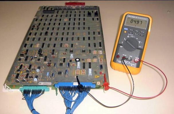
In order to adjust an Atari power supply, you will need a multimeter and test probes. A multimeter is the grown-up cousin of the voltmeter. Strictly speaking, a voltmeter is only capable of measuring voltage, while a multimeter can typically measure voltage, current, resistance, and sometimes much more. Folks tend to be a little imprecise and refer to the two types interchangeably. These instructions deal specifically with using a digital multimeter (sometimes called a DMM), as opposed to an analog multimeter. Practically speaking, the difference between the two is that the DMM has a digital display and the analog meter has a swinging needle instead. Chance are that if you buy a meter nowadays you're going to wind up with a DMM, so the following instructions assume that's what you are using. The meter shown above is a Fluke 87 True RMS Multimeter and goes for about $350. There's no need to get this high-end of a DMM for what we're going to be doing next. You should be able to find something adequate for about $20.
Notice that there are two test probes (also known as "leads") connected to the meter and the PCB (in this case, a Tempest). These probes happen to have clips on one end to free up the users hands, but more traditional probes are fine too - you'll just have to hold them in contact with the test points when making your measurements. We'll show you the test points in a minute, once we get the meter set up properly.
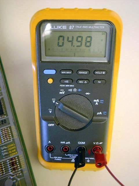
In the picture above, you'll see that we've got the black test lead connected to the COM input, and the red test lead connected to the V-Ohm-Diode input. There's nothing magical about the colors, it's just traditional that black is usually used for ground connections, and red is usually used for non-ground connections. Your meter will probably have a COM input but the other one might be labeled differently that the meter shown above. The important thing to be aware of is you must not plug it into any input with an "A" in the label (like mA for example). That type of input is for measuring current (in Amps), which we won't be doing. It'll blow a fuse in the meter if you accidentally get it wrong, but it won't damage the game any. Relax!
You'll also notice that the selector knob is on the "V" with a solid, straight line above it. That means that the meter will display DC Volts. There's also a "V" with a wavy line above it - that's for measuring AC volts. We're only going to measure DC Volts here. This meter happens to be an auto-ranging meter, which means that the display will automatically change to ensure that it can properly display the measurement. Chances are that any DMM you've bought since 1990 is also auto-ranging, but if it's not then you'll need to make sure that the measurement range you select can accommodate voltages between 0 and 10 volts DC. A larger range is OK, the measurement just won't be as accurate. Now, let's show you where to connect the other end of the test leads.
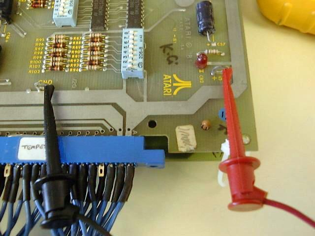
You'll notice that the black lead is connected to one of many test points labeled GND, and the read lead is connected to a +5V test point. It doesn't really matter which exact pair of test points you use, as long as one is labeled GND and the other is labeled +5V. On some Atari boards, the metal test points weren't installed, but you'll be able to see where they were supposed to go, and can use those locations intead. You may find other test points like +22V, -22V, X OUT, etc. depending on which game you're working on, but let's ignore them and just stick to the +5V adjustment work.
Once you've got your connections make, make sure that all the connectors to the game PCB are connected before you turn on the power. Go ahead and turn the game on when you are ready. Ideally, the measured voltage should be from about 5.05V to 5.10V. In our illustration above, the measured voltage is 4.97V in the first picture and 4.98V in the second. If the voltage displayed on your DMM is just slightly too high or too low, then you may be able to adjust the voltage to bring it into the ideal range. If the voltage displayed is significantly different (anything below 4.5V or higher than 5.5V) then there's something wrong with your power supply that an adjustment won't fix. You should turn your game off ASAP if that's the case.
Assuming that your adjustment is just slightly off, let's try to bring it back into the ideal range. The adjustment pot (short for "potentiometer") is located on the Regulator/Audio board, not on the game PCB itself. It's frequently got a glob of RTV silicone on it to prevent the adjustment from shifting position during shipping. It's OK to remove it.
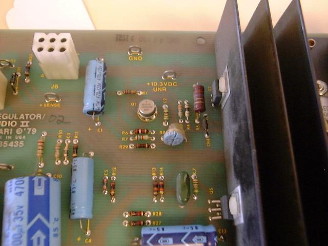
Turn the dial slightly as you check the DMM to make sure you are turning in the correct direction. If you reach the limit of travel of the knob and you still haven't achieved the desired voltage, then something else is wrong.
Well, that's the only power supply adjustment you can make on a vintage Atari game. If you think maybe your power supply or game PCB is bad, please consider choosing Elektron Forge for your repair needs.
Created on 2/25/05